From Friday, April 19th (11:00 PM CDT) through Saturday, April 20th (2:00 PM CDT), 2024, ni.com will undergo system upgrades that may result in temporary service interruption.
We appreciate your patience as we improve our online experience.
From Friday, April 19th (11:00 PM CDT) through Saturday, April 20th (2:00 PM CDT), 2024, ni.com will undergo system upgrades that may result in temporary service interruption.
We appreciate your patience as we improve our online experience.
Use a basic 5mm LED (Light Emitting Diode) to output light using digital line output on your myDAQ device.
A basic 5mm LED is a low-cost solution for emitting light for various applications. LEDs are often used to indicate if something is turned on, what power level a machine is running at, and for low-cost lighting solutions in remote locations. It is important to know that a LED is a diode, which only allows current to flow in one direction. This means that we have to connect the positive input to the positive lead of the lead, and the negative input to the negative lead. Also, a LED can only handle a certain amount of current, so it is necessary to connect a resistor in series to regulate the current flow.
Figure 1: Basic Red 5mm LED and 330Ω Resistor
The LED is wired in series with a 330Ω resistor. Assuming the LED has negligible resistance, the total resistance of the circuit is 330Ω. According to Ohm’s Law, the current drive with a 5VDC power supply from the digital line would result in 5V÷330Ω= 15.15mA. As stated in the specification sheet for the LED that is referenced at the bottom of the document, the Led can handle a current up to 20mA, and is recommended to be used with 16 to 18mA; so at 15.15mA we will be safe. The LED requires a positive input on the longer lead side and a negative input on the shorter side, as seen in Figure 1 above. We will supply power to this circuit using Digital Line 0 of the myDAQ, and ground the circuit to Digital Ground of the myDAQ.
Figure 2: Wiring Diagram
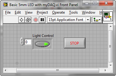
The user interface we created has a Boolean push button switch, Light Control, to turn the LED light on or off.
Figure 3: LabVIEW Front Panel
In LabVIEW we need to create a front panel Boolean array control to output a 5V digital signal on Line0 to our basic 5mm LED. This Boolean value is input into our DAQ Assistant which will output the corresponding value to the NI myDAQ digital port. In digital Boolean logic, a True corresponds to a 5V signal, and a False corresponds to a 0V signal. Therefore, a True will turn on the LED.
Figure 4: Coding Block Diagram
The LabVIEW diagram looks very similar to the coding block diagram, except the LED is not included.
Figure 5: LabVIEW 2009 Block Diagram
(The attached LabVIEW code snippet can be dragged-and-dropped to a LabVIEW block diagram, use attached PNG file. After locating the PNG file, just drag the file icon onto a blank block diagram, as if you were dragging the file onto your desktop.)
Inside the while loop on the left is the Boolean Array Control used to send a True or False to the LED. The control is on the front panel, and can be seen to have only one element in the array. This is because the DAQ Assistant is setup to only output to one line. On the right is the DAQ Assistant. It’s configured to output a single value from the myDAQ Digital Port0/Line0 each time it executes. All of the code inside the While Loop continues to run until the Stop button is pressed on the front panel. The Wait VI (top left) delays execution of the while loop to every 100ms. Therefore the output rate is 10 samples per second, or 10 Hz.
In this VI the DAQ Assistant is configured for on-demand output on the digital channel. The following steps walk through the configuration of the DAQ Assistant from scratch:
Figure 6: DAQ Assistance Resistance Configuration
*Note that sample time is set by the Wait VI and is set to sample 10 times per second (every 100ms) in this VI
Example code from the Example Code Exchange in the NI Community is licensed with the MIT license.


