Advanced Encryption Standard (AES) for LabVIEW FPGA
- Subscribe to RSS Feed
- Mark as New
- Mark as Read
- Bookmark
- Subscribe
- Printer Friendly Page
- Report to a Moderator
Code and Documents
Attachment
Introduction
Advanced Encryption Standard (AES), or Rijndael as it can also be referred to, is a block cipher that has been received as the standard for encryption by the United States government. Being a block cipher, this encryption method takes a group of bits that is of a fixed size, performs the actual encryption, and then has an output that is also the same size of bits as the input. This method uses a secret key of a varying size in conjunction with the plain text input data in order to create the encrypted data of the same size. The decryption method of the data works in the same way by taking the encrypted data along with the secret key to produce the original data. The fixed block size for the data that the AES method takes is 128 bits while the key can be 128, 192, or 256 bits. The 128 bits means that the block that the AES operates on is a 4x4 square of bytes.
Implementation
Implementing the AES method with a RIO device involves several steps that are described at a high level below. This is broken up in two different sections, one for the host, and one for the FPGA itself.
Host
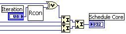
- The first step in the code is the key generation which occurs on the host. In this step the user will provide a secret key which is then expanded by using Rijndael’s key schedule. The short key is expanded into a larger one. A 128-bit key is transformed into a 176-byte key, a 192-bit key is transformed into a 208-byte key, and a 256-bit key is transformed into a 240-byte key. The key schedule will take a 4-byte subset of the key as a number U32 and an iteration count and send this data to the key schedule core, which returns a U32.
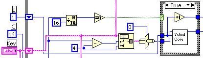
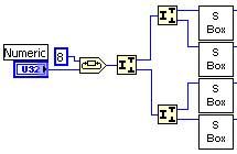
- The key schedule core first performs a byte rotation on the key and splits the U32 into individual bytes and sends them to have Rijndael’s S-box applied. This is used to obscure the relationship between the key and the cipher text.
- The next step in the core scheduler is the Rcon step. This takes the first byte of the output word (from the S-box) and performs an XOR on the byte with the result of the Rcon step, which is essentially an exponentiation of 2 to the iteration count of the key schedule.
- The key schedule core first performs a byte rotation on the key and splits the U32 into individual bytes and sends them to have Rijndael’s S-box applied. This is used to obscure the relationship between the key and the cipher text.
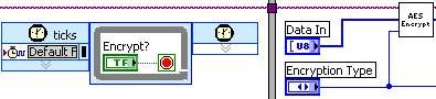
- After the key has been generated, information about the key, the type of encryption to perform, as well as the key itself, needs to be transmitted to the FPGA. The key is transformed into a byte array, and sent one byte at a time along with an interrupt to ensure the FPGA receives all the data in the correct order.
- The Host will then send basic commands to the FPGA stepping the data through both the encryption and decryption process before finally returning the data back to the user.
FPGA
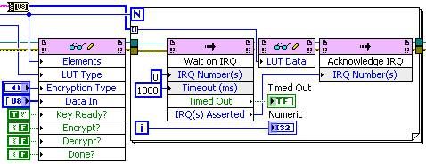
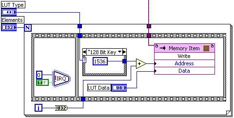
- In order for the FPGA to be able to perform the cryptography it is ideal to store the key in a look-up-table (LUT). For this, we will be using a VI-scoped memory item. As there are multiple cryptographic algorithms out there, the LUT can be used to store many different keys which will provide user flexibility.
- Once the key information has been provided from the host, the encryption can take place as soon as the host gives the signal. The encryption will first generate what is called a round key which is derived from the key schedule. It will then begin the iterative process to perform the actual encryption.
- The first iteration of the encryption algorithm will combine each byte of the state with the round key using a bitwise XOR.
- The bulk of the iterations (called rounds) will perform a non-linear substitution which replaces each byte with another according to a pre-defined LUT. Then each row of the state will be shifted cyclically. After which there will be a mixing operation which takes place on the columns and combined the four bytes of each column, and then the round key will be added again.
- The final iteration is similar to the previous ‘n’ rounds, without the column mixing operation.
- The first iteration of the encryption algorithm will combine each byte of the state with the round key using a bitwise XOR.

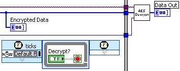
- After the encryption has completed the encrypted data is available for the host to read while the FPGA will wait until it receives the signal to decrypt the data. This example has the same FPGA encrypt and decrypt the data, however the same steps would take place if the data were to be stored and later decrypted or even transmitted between RIO devices prior to decryption. This operation itself is done in a similar fashion as the encryption.
Example code from the Example Code Exchange in the NI Community is licensed with the MIT license.
