From 04:00 PM CDT – 08:00 PM CDT (09:00 PM UTC – 01:00 AM UTC) Tuesday, April 16, ni.com will undergo system upgrades that may result in temporary service interruption.

We appreciate your patience as we improve our online experience.

Example Code

Archived: Digital Waveform Generator: Using the NI6551 Instrument in NI Multisim

Code and Documents

Attachment

Overview


This document has been archived and is no longer updated by National Instruments.

This example program which include NI Multisim and NI LabVIEW is one in a series which showcases the power of using advanced LabVIEW instruments within the simulation environment.

All instruments are based upon a virtual instrument template found in the Multisim sample folder. Any LabVIEW user can easily take this template and define an instrument which can input complex signals, or visualize simulation data within Multisim.

This level of advanced design flexibility is only available to the professional design engineer with the National Instruments platform of Multisim and LabVIEW.

Please Note

SPICE simulation, the language by which Multisim emulates circuit design behavior, does not run in real-time. This means that if a real-world signal is acquired by a LabVIEW instrument it cannot be directly injected into simulation, since the measurements will be running at different rates (real time vs. simulated time).


Purpose Of This Instrument

When validating both simulated designs and prototypes, it is important that the variable factors that will affect the measured output be minimized. This means that one of the best ways in which to coordinate the test and verification during both stages of the design flow is to use the same input.

The NI6551 waveform generator is such an instrument that allows you to emulate the look and behavior of the same instruments that will act as a prototype stimulus. In this instrument you can input a pre-defined waveform, or generate one during the validation process.

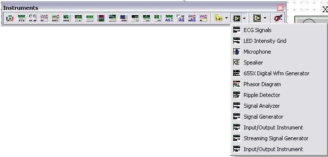
This LabVIEW instrument, built custom for NI Multisim acts as a stimulus for a digital circuit. Since this instrument is built in LabVIEW we have a number of built-in analyses, and easy-to-use features in the instrument. In this case we are able to generate a digital waveform pattern which will create up-to 21 channels of digital test vectors.


Installation Instruction

Download the archived file to the desktop. You simply need to:

  1. Close NI Multisim if open.
  2. Open the attached 5926_waveform_gen.zip file.
  3. Select My Computer.
  4. Browse to C:\Program Files\National Instruments\Circuit Design Suite 10.1\lvinstruments.
  5. Save the NI655XGenerator.llb file from the zip file to this folder.


Instrument Features

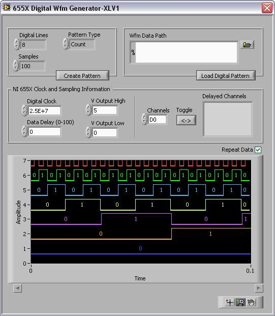
The NI655X digital waveform generator consists of multiple controls and settings.

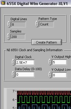
You can set the number of Digital Lines as test vectors in the instrument.

The samples setting, defines the number of samples in the test vector.

The Wfm Data Path allows you to create test vectors based upon an external input. This means that the same digital waveform used in prototype/physical test, can be used in the simulation stages also.

Finally you are able to set the NI 655X Clock and Sampling Information settings, such as the digital clock setting, data delay and the V Output (High and Low).

In the bottom right-hand corner of the waveform generator are the visualization tools for zoom and pan, to view the test data.


Using the Instrument and Example Circuit

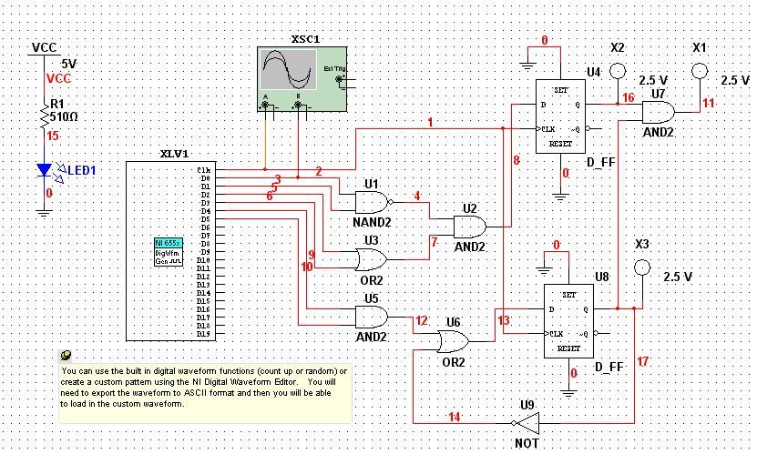
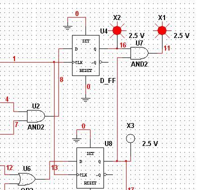
This instrument will use the example circuit that is in the attached 5926_waveform_gen.zip file folder.

  1. Open Multisim by selecting Start > All Programs > National Instruments > Circuit Design Suite 10.1 > Multisim 10.1.
  2. Go to File > Open.
  3. Browse to the NI655X Demo.ms10 file from the 5926_waveform_gen.zip file.
  4. In Multisim select the LabVIEW icon in the instrument toolbar (as seen below).
  5. Select 655X Digital Wfm Generator. This is the name of the Waveform Generator instrument (as seen below).


  1. Place the instrument onto the schematic as seen below, and connect it to the pins ranging from CLK to D5.
  2. The circuit is now complete.


  1. Double-click on the XLV1 instrument (the NI655X generator stimulus)
  2. Set the Digital Lines to 8.
  3. Set the Samples to 200.


  1. You are now ready to begin simulating the circuit.
  2. Click on the run button on the simulation toolbar.

  1. You will see the red indicators (X1, X2 and X3) blink on and off as the test vectors propagate through the circuit.
  2. Stop the simulation (by selecting the stop button in the simulation toolbar).
  3. Double-click on the XLV1 instrument (the NI655X generator stimulus)
  4. Click on the File Open icon in the Wfm Data Path section of the instrument.
  5. Browse to the DWE Test Pattern.txt file. This file contains a set of waveforms that have been used in the test of the physical prototype of a digital circuit. This means we are closing the loop between simulation and hardware by validating with the same data in both stages of the design flow.
  6. Run the simulation and view the change in the ECG signal in the oscilloscope.
  7. Click on OK.
  8. Click on the Load Digital Pattern button, to load the waveform data.
  9. Click on the run button on the simulation toolbar.
  10. View the simulation run based upon real data.


Example code from the Example Code Exchange in the NI Community is licensed with the MIT license.

Contributors